Mechanized tunneling is a highly automated construction process that has proven itself to be suitable for use in a wide range of different geological and hydrological conditions. Its application ranges from urban tunnels driven below sensitive structures with low ground cover to deep alpine tunnels characterized by large ground pressures and high overburdens. Earth Pressure Balance (EPB) shield machines are widely used in mechanized tunneling of soft and mixed ground in recent years due to their applicability in an increasingly large range of ground conditions and lower cost compared to slurry shields. In the tunneling operation with EPB shield machines, the excavated soil is used as the support medium to maintain the stability of the tunnel face. During the excavation process, the property of the in-situ ground in front of the cutterhead is modified by injecting conditioning materials in front of the cutterhead before it is excavated and transported into the pressure chamber through the openings on the cutterhead. The soil paste circulates inside the chamber by the stirring action of the cutterhead rotator arms and a number of rotating as well as fixed mixing arms. It is then discharged out of the chamber towards the back-up trailer through the conveyor system under the control of the rotating screw. [1]
Since in EPB shield machines the pressure distribution at the cutting face is transient and depends on the material transport characteristics, one major research question investigated in Subproject C4 of the Collaborative research Project SFB 837 is to investigate the influence of the design of the pressure chamber and the rheological properties of the soil-foam mixture. Another major research question is related to the influence of the chamber design on the efficiency of the material transport from the cutterhead towards the screw conveyer attached to the bulkhead of the pressure chamber of the machine. To this end, a computational model for the simulation of material flow in different EPB chambers has been developed [2]. The flow equations of the excavated soil paste, modeled as a compressible non-Newtonian fluid, are solved by the Finite Element method. The interaction of the rotating interior components in the chamber with the soil paste is enabled by means of Immersed Boundary and Shear-Slip Mesh Update method. Two realistic numerical models, based on a Herrenknecht (TBM 1) with a diameter of 7 m and a Hitachi EBP shield machine (TBM 2) with a diameter of 17.5 m as shown in Fig. 1, were considered for the study of pressure distribution. The relative pressure profiles measured at the monitoring points located on the bulkhead were investigated.
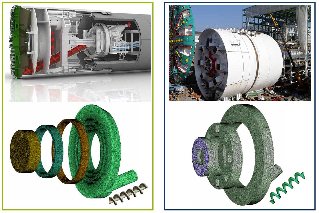
Fig.2 shows that the pressure distribution highly depends on the machine design as well as the material properties of the soil paste mixture. When the soil paste is adequately compressible, there exists a pressure unbalance between the left- and right-hand sides of the chamber, which is consistent with in-situ observations. The pressure in TBM 1 strongly fluctuates when the compressibility of the soil paste decreases, which is relevant for the case of a high pressure level in the chamber or lack of foam conditioning. In contrast, no large pressure fluctuations are observed in TBM 2, which implies, that the pressure is more stable with respect to the change of material properties in this design [3].
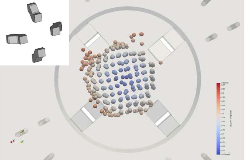
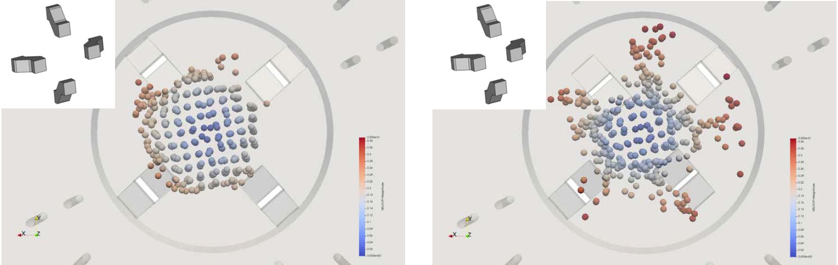
The efficiency of material transport in the center zone of the chamber was studied by considering different configurations of the cutterhead rotators, as shown in Fig. 3. It was shown, that a non-symmetric arrangement of the rotators leads to a significantly improved performance in terms of expelling the material out of the center zone towards the screw conveyor [4]. In contrast, for the symmetric configuration, the material stays longer in the center zone of the chamber, which increases the risk of clogging and degradation of material properties.
The article "Transformer model for sensitivity analysis of steel and steel-fiber reinforced concrete
more...
Chen Xu presented his doctoral theses with the title "Physics Meets Data: Machine Learning Framework
more...